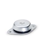
Type: A - With two-hole flange (d1 = 60 / 90 / 113 mm)
Overview of Types Vibration Damping Elements / Vibration Isolation Mounts / Rubber Bumpers
Guide to Selecting Vibration Damping Elements
Plastic Characteristics
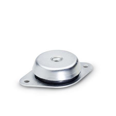
Product description
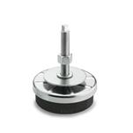
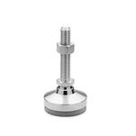
Leveling feet GN 148 are designed for limiting vibration on heavy machinery, thus increasing the lifetime of the machines and reducing noise pollution.
The structure of these feet helps absorb horizontal forces. The version with tear-off lock (identification no. 2) protects the feet from destruction caused by tear-off under excessive tension loads.
The information about load bearing capacity are non-binding guide values and rule out any liability. They constitute no general warranty of quality and condition. The user must determine from case to case whether a product is suitable for the intended use.
Specification
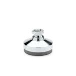
Vibration damping element
Natural rubber (NR)
- Vulcanized
- Operating temperature up to 176 °F (80 °C)
- Hardness Shore A ±5
- Soft43
- Medium57
- Hard68
Sheet metal / Threaded insert
Steel, zinc plated, blue passivated finish
RoHS