GN 1440 Telescopic Slides Steel, with Full Extension, Load Capacity up to 731 lbf

Telescopic Slides GN 1440: Steel, with Full Extension, Load Capacity up to 731 lbf
Type: B - With rubber stop

Product description

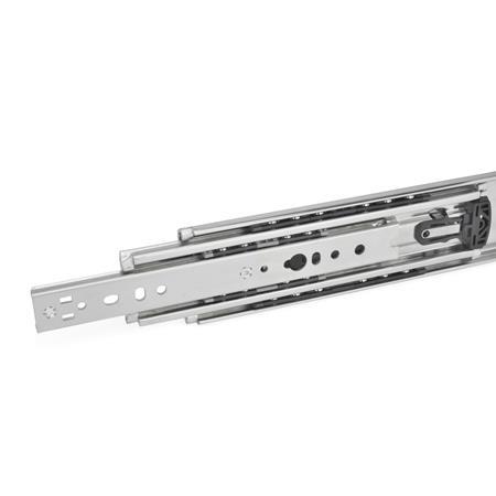
Telescopic slides GN 1440 are installed vertically and in pairs. The stroke reaches ≈100 % of the nominal length l1 (full extension). Patented plastic ball cages ensure extremely smooth running of the slide.

Telescopic slides of various types, for example, with and without latch, can be combined freely, which is why GN 1440 is delivered as a single unit and not in pairs. Due to the symmetrical mechanical design, the types B and K can be mounted on either the left or right side of the extension.

All mounting holes are easy to reach through auxiliary holes. Only the mounting holes are shown, but other production-related holes may be present.

Specification

Slide profile
Steel
Zinc plated, blue passivated finishZBZB


Bearings
Roller bearing steel, hardened


Ball cage
Plastic


Latches

  • Zinc die-cast
  • Plastic

Rubber stop
Plastic


Operating temperature
-4 °F to 212 °F (-20 °C to +100 °C)


RoHS

On request

  • Other lengths and hole distances
  • Other mounting options
  • Other finishes
Hide technical drawing
GN 1440 Steel Telescopic Slides, with Full Extension, Load Capacity up to 731 lbf sketch

Part Options / Table

Type

BWith rubber stop
KWith rubber stop, latch in extended position

Identification no.

1Mounting with through holes
Show / Hide columns

Metric

Dimensions in: Inch (change to Metric)
l1l2 +0.158 / -0.158
Stroke
l3Fs per pair
at 10,000 cycles

at 100,000 cycles
11.8111.73223.07506 lbf (2250 N)354 lbf (1575 N)
15.7515.66930.94562 lbf (2500 N)393 lbf (1750 N)
19.6920.15739.37585 lbf (2600 N)405 lbf (1800 N)
23.6224.01647.17618 lbf (2750 N)432 lbf (1920 N)
27.5627.87454.96663 lbf (2950 N)506 lbf (2250 N)
31.5031.73262.76697 lbf (3100 N)489 lbf (2175 N)
35.4335.59170.55719 lbf (3200 N)506 lbf (2250 N)
39.3739.37078.27731 lbf (3250 N)511 lbf (2275 N)
47.2447.71794.49663 lbf (2950 N)455 lbf (2025 N)
59.0659.213117.80506 lbf (2250 N)354 lbf (1575 N)

Build & Price

Length l1
Type


Identification no.

Finish
Zinc plated, blue passivated finish
Length l1
Type


Identification no.

Finish
Zinc plated, blue passivated finish

Mounting Holes - Outer Slide

45f040a2-6a1e-4640-8ffb-d4c6cf1ad5fb
Show / Hide columns
l1a6a7a8a9a10a11a12a13a14a15a16a17a18
300--------161173193213228
400--------261273293313328
500--------361373393413428
600213228363378----461473493513528
700213228363378----561573593613628
800313328463478----661673693713728
900313328463478----761773793813828
1000413428563578----861873893913928
120031332846347871372886387810611073109311131128
15004134285635789139281063107813611373139314131428

Mounting Holes - Inner Slide

04ab9ccc-04f3-46a5-89d8-fbddb550519f
Show / Hide columns
l1i5i6i7i8i9i10i11i12i13i14i15i16i17
300---------173**-213228
400-161------261273273313328
500-229------361373373413428
600213228398413----461473473513528
700313328463478----561573573613628
800313328498513----661673673713728
900413428563578----761773773813828
1000413428598613----861873873913928
120031332846347871372886387810611073107311131128
15004134285635789139281063107813611373137314131428

  • The bore is only usable on types B and K.
    ** The bore is only usable on types B, MR and ML.

Mounting Screws

For the listed loading forces FS to be absorbed reliably in the surrounding structure, all available through holes of the outer and inner slide having a Ø of 6.6 mm must be used. Alternatively, holes with a Ø of 5.2 mm are available. The slotted holes, Ø 6.6 x 3.4 mm, facilitate adjustment during mounting. Failure to use mounting screws reduces the load capacity. The following screws can be used for mounting:

Designation - Standard
Socket button head screw ISO 7380
Low head socket cap screw DIN 7984 / DIN 6912

Outer Slide
M 5 / M 6
M 5

Inner Slide
M 5 / M 6
M 5

Rubber Stop

Type B with rubber stop

b51a3be5-5d5a-4fe5-a1e0-63e33814175c

The rubber stops dampen the impact of the slide in the two end positions. This feature minimizes noise development and increases the service life. Attached to the slides in a partially concealed, partially visible manner, the stops meet each of the requirements in regards to shape, material, and hardness.

If larger static or dynamic loads occur in the direction of extension, they should be absorbed by additional end stops.

Types MR / ML with rubber stop, latch in retracted position

66cdf919-95b2-438c-b8e4-7f3fd022bcfc

Types MR / ML are used in applications in which the slide needs to be locked in the back end position. This feature prevents the slide from extending on its own, for example due to an inclined position. If larger loads occur in the direction of extension in the latched position, they should be absorbed by additional latch elements.
When closed, the latch mechanism locks into place under spring load via a recess on the outer rail. Pressing the release lever releases the inner and middle slide for extension. Back in the retracted position, the mechanism automatically locks into place again via the recess on the outer slides by moving over a ramp.

Type K with rubber stop, latch in extended position

0a3dd7fa-14ec-429b-b0a3-6c52146497b9

Type K is used when the extension is to remain in the extended position for a certain amount of time. This feature allows maintenance work to be performed with the slide being extended, for example. If larger loads occur in the latched position, they should be absorbed by additional latch elements.

For the function to be activated, the slide has to be fully extended to the front, where it will automatically lock into place via a pretensioned latching lever. Pressing the lever releases the slide, allowing the slide to retract again.

Types QR / QL with rubber stop, latch in extended and retracted position

8b48c6f4-432e-4022-bfd7-828312e16956

Types QR / QL combine the features of types MR, ML and K. The inner and middle slide lock into place in the two end positions.
In contrast to the locking of type K, types QR / QL are operated via an internal linkage Pressing the green release lever activates the locking rocker, releasing the slide rail for retraction or extension.

Load Capacity

The maximum load capacity of telescopic slides depends on the slide cross-section and the nominal length l1 as well as the resulting stroke l2. Furthermore, the extension width, the slide materials used and the components of the equipment options, such as the dampened self-retracting mechanism, have a corresponding influence.
The information on the maximum load capacity of the telescopic slides was determined in endurance tests under the following conditions:

  • Slide arrangement in pairs, side mount
  • Observance of all mounting information
  • Warp-resistant test setup
  • Equal distribution of the maximum load FS over the entire extension area
  • Standard slide spacing of 450 mm
  • 10,000 or 100,000 test cycles (one extension and one retraction = one cycle)
  • Gradual increase of the load

248bf1bb-4ab4-47b4-9941-9fa07db81d43

Wear, performance, and maximum bending were assessed after each test section.

Selected Part

Total (net)
US$141.27
Call / Email for Delivery Time
Save as Favorites
Recommend a product
Please note our quantity discounts (US Dollars).
MinMaxPrice
19US$141.27
1024US$129.50
2549US$117.73
≥ 50US$105.95
Prop 65: Not compliant
WARNING:
Cancer and Reproductive Harm - www.P65Warnings.ca.gov
RoHS: Compliant
This article is RoHS-compliant in application of Annex III., which means it complies with EU Directive 2011/65/EU, including extension (2015/863/EU), for restricting the use of certain hazardous substances in electrical and electronic devices. The Directive regulates the use of hazardous substances in devices and components. The implementation in national law is summarily described with RoHS(Restriction of (the use of certain) hazardous substances)).
Weight: 3.042 lbs
If weight is not listed, please contact our Sales Department for additional information regarding weight.
Phone: 800-877-8351

CAD Download

Other Data Formats

Email CAD File

To receive an email with a CAD download without creating an account, please enter your e-mail address. Max of 3 CAD files per day unless you create an account.

CAD Download Tutorial About CAD Downloads

Need Help?

Our service team is available from Monday to Friday between 7:30 AM and 5:00 PM Central Time: 800-877-8351

Special Requests | Contact our sales team

GN 1440-300-B-1-ZBGN 1440-300-K-1-ZBGN 1440-400-B-1-ZBGN 1440-400-K-1-ZBGN 1440-500-B-1-ZBGN 1440-500-K-1-ZBGN 1440-600-B-1-ZBGN 1440-600-K-1-ZBGN 1440-700-B-1-ZBGN 1440-700-K-1-ZBGN 1440-800-B-1-ZBGN 1440-800-K-1-ZBGN 1440-900-B-1-ZBGN 1440-900-K-1-ZBGN 1440-1000-B-1-ZBGN 1440-1000-K-1-ZBGN 1440-1200-B-1-ZBGN 1440-1200-K-1-ZBGN 1440-1500-B-1-ZBGN 1440-1500-K-1-ZB

Your Contact

You are looking for a Winco partner near you?

JW Winco Services

Our service team is available from Monday to Friday between 7:30 AM and 5:00 PM Central Time

Request Callback