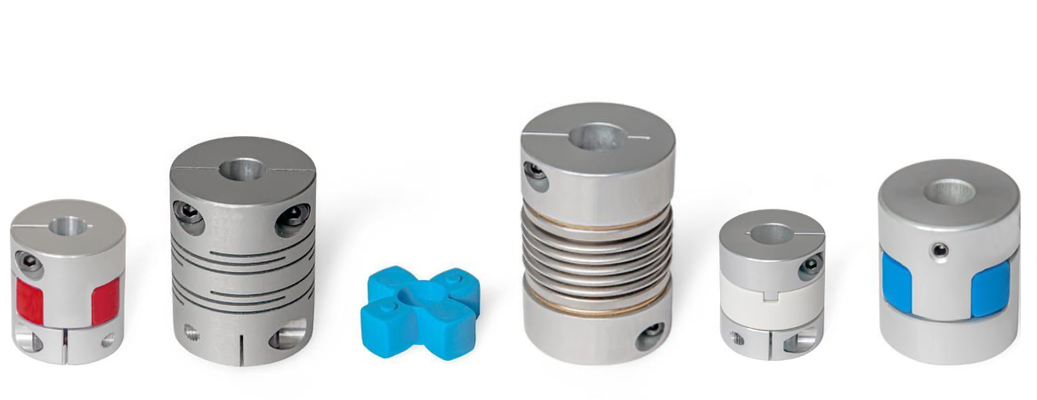
All couplings at a glance!
Misalignment and runout tolerances
Shaft offset and runout errors
Like all mechanical parts, shafts are subjected to manufacturing and assembly tolerances that generally cannot be eliminated entirely, even with extensive technical measures. If these deviations are not taken into account in the design, it can result in vibrations, running noises, and wear or damage to the shafts and their bearings. Suitable couplings not only are able to effectively compensate for misalignment and runout errors, they also greatly simplify the assembly process, thereby reducing the overall labor required. Shaft offset and runout errors can vary in nature and should always be taken into consideration when selecting the appropriate coupling.
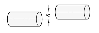
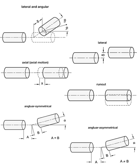
Error: Radial
The axes of the shafts are in fact parallel, but they are offset laterally and do not line up.
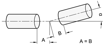
Error: Angle
The axes of the shafts do not lie on the same plane, but meet at a certain angle.
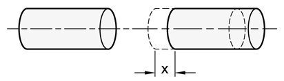
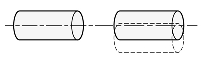
Error: Axial
The shafts move axially along the axis of rotation.
Error: Runout
The shafts move radially out of the center of the axis of rotation.
Uses and applications, coupling types
The applications of couplings can generally be divided into two classes.
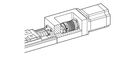
Motion control
The rotational movement is transmitted with very high precision and accuracy for position and motion control applications. This requires a coupling type with a high torsional stiffness and zero backlash in the direction of rotation. Typical applications include: Servo and stepper motors for linear axes, industrial robots, test benches, etc.
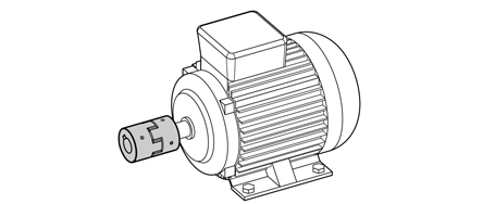
Torque and power transmission
For torque and power transmission, the focus lies on pure transmission of force. This requires couplings that can withstand high torques and heavy loads while functioning reliably in harsh conditions. Typical applications include: Conveyor systems, pumps and agitators, packaging machines, etc.
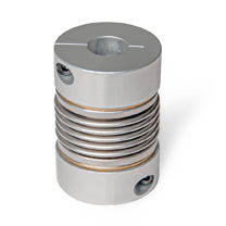
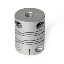
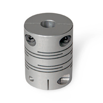
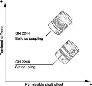
Bellows couplings and beam couplings
Metal bellows couplings offer high torsional stiffness. This makes them excellent for precise and controlled movements.
Beam couplings have lower torsional stiffness compared with bellows couplings, but they can compensate for higher shaft misalignments.
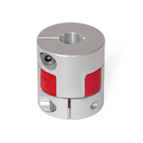
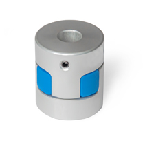
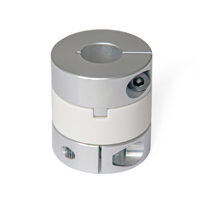
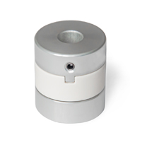
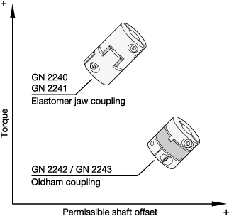
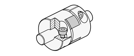
Elastomer jaw couplings and Oldham couplings
Elastomer jaw couplings are designed for high torque transmission and can be used in all manner of applications.
Oldham couplings transmit less torque but can compensate for higher shaft misalignments.
Mounting Information
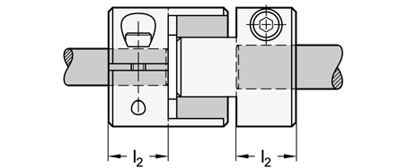
Shaft insertion depth
For correct fastening of the coupling hubs, the shaft must be installed according to the recommended shaft insertion depth l2. The shaft insertion depth l2 is specified in the standard sheet of the respective coupling.
If the insertion depth is too low, the shaft could slip out of the coupling, or the clamping hub could break. If the shaft is inserted too far, this can cause interference within the coupling, leading to damage.
Shaft offset compensation
Like all mechanical parts, shafts are subjected to manufacturing and assembly tolerances that generally cannot be eliminated entirely, even with extensive technical measures. Couplings can compensate for the resulting misalignments while still ensuring transmission of the necessary torque.
However, if the misalignments exceed the permissible values, it will cause vibrations that can quickly shorten the service life of the coupling. For that reason, the actual shaft offset may never be larger than the specified permissible values.
The permissible shaft offset values given in the standard sheet only take the lateral, angular or axial misalignment into account. In the event of combined misalignments consisting of two or more errors, each permissible value is reduced to half the value specified in the standard sheet.
In general, it is recommended to limit misalignments to no more than one third of the permissible value in the standard sheet. This is because shaft misalignment not only occurs during assembly, it often develops during operation as the result of vibrations, thermal expansion or bearing wear.
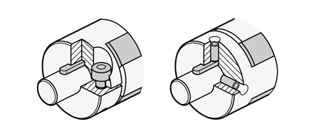
Shaft-hub fastening
The right type of fastening must be selected to ensure simple and reliable mounting of the coupling hub on the shaft. The following shaft-hub fastening types are available:
Clamping hub
The fastening with clamping hubs is entirely non-positive by reducing the slit height using socket cap screws. In this type, the coupling hub is fastened simply and securely with a high clamping force, without damaging the surface of the shafts.
Grub screw
When used for fastening, grub screws are inserted radially to create a positive and non-positive connection to the shaft surface. Alignment holes bored into the mounting diameter allow the coupling hub to be positioned precisely. At the same time, this prevents damage to the clamping point.
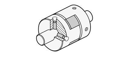
Combination with keyway
The combination of grub screw or clamping hub fastening with feather keys prevents slip torque while ensuring precise angular positioning of the shafts. This type of fastening also provides for maximum torque transmission.
Technical information / Definition of terms
The torque that the coupling can continuously transmit. This value takes into account load fluctuations during operation, so that no reduction of the nominal torque is required when selecting the coupling (except for cross-slide couplings). The coupling should be selected so that the load torque generated during continuous operation does not exceed the rated torque.
The torque that the coupling can transmit in the short term.
The maximum speed of the shaft coupling was calculated based on the circumferential speed 33 m/s. Tests have confirmed that at this speed the shaft coupling is not damaged.
Specifies the inertia or rotational resistance of the shaft coupling when rotating around its own axis. The lower the moment of inertia, the lower the load torque when the motor starts and stops.
The static torsional stiffness indicates by how many degrees a shaft coupling twists as a function of the applied torque. Usually, the torsional stiffness is given in torque per radian (Nm/rad). To facilitate design, torsional stiffness can also be converted to degrees per Nm.
In this case, the following applies:
2π rad = 360° → 1 rad = 360°/2π = 180°/π ≈ 57.3°.
Example:
Shaft coupling with a torsional stiffness of 500 Nm/rad = 500 Nm/57.3° → reciprocal 57.3°/500 Nm ≈ 0.1146°/1 Nm
Slip torque refers to the torque at which the shaft begins to slip out of the clamping hub. This presumes that the clamping hub was installed at the specified screw tightening torque.
The slip torque values given in the table were derived from experimental testing. They are based on a shaft tolerance of h7, a shaft hardness of 34 to 40 HRC and the screw tightening torque for the clamping hub given in the table.
The load torque must be less than the slip torque for which the coupling is designed. It is also necessary to take into account that the slip torques given in the table are lower than the indicated maximum torque values. If no slip torque is specified, then the maximum torque can be achieved.
Because the slip torque changes due to operating conditions, the suitability of the selected coupling should be tested under real conditions.
If the ambient temperature is greater than 86 °F (30 °C), the rated torque and the maximum torque must be adjusted using the temperature correction factors.
The diagrams show the change in static torsional stiffness within the permissible operating temperature range, under the assumption that the static torsional
stiffness at 68 °F (20 °C) is 100 percent. The torsional stiffness of the couplings decreases with increasing temperature.
When the shaft ends are installed in eccentric arrangements, the coupling constantly attempts to return to its neutral position. The resulting force is referred to as restoring force.
If the couplings are installed with the lowest possible eccentricity, the resulting restoring forces are lower. This also reduces the force acting on the shaft bearing.
The graphs show the relationship between the force and the eccentricity.
If the coupling is under pressure, subject to compressive load in the axial direction, it will strive to return to its neutral position. The force that counteracts the compressive force is referred to as restoring force.
Lowering the compression acting on a coupling results in a lower restoring force and less force exerted axially. This must always be taken into account in dimensioning the coupling.
The graphs show the relationship between the force and the compression.