 Original design
code: DD51
Installation (front view): AN - On the chamfer, above
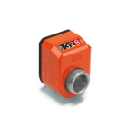
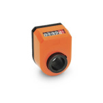
Color: OR - Orange, RAL 2004, shiny finish
Color: OR - Orange, RAL 2004, shiny finish
Application Video EN 954 and EN 9054
Overview of Digital Position Indicators, with Hollow Shaft
ISO Fundamental Tolerances
Plastic Characteristics
Product description
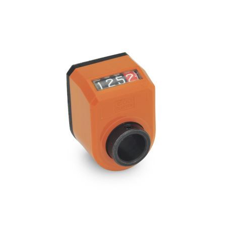
Digital position indicators EN 954 have a direct coupled drive with digital indications. The digits are easy to read and appear enlarged due to the magnifying effect of the viewing window.
Both housing sections are ultrasonically welded, making the housing particularly stable and compact. The foam rubber seal prevents the transmission of vibration to the counter and serves as a seal.
Specification
Housing
Plastic, Polyamide (PA)
- Color
- Orange, RAL 2004, shiny finishOR

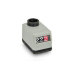
- Gray, RAL 7035, shiny finishGR

- Black-gray, RAL 7021, shiny finishSG

- Orange, RAL 2004, shiny finishOR
- Operating temperature
32 °F to 176 °F (0 °C to +80 °C) - Oil and solvent resistant
Sight glass
Plastic, polyamide (PA-T), transparent
Counter
- White numbers
- Black number wheels integers
- Red decimals with additional scale
Shaft receptacle
Steel, blackened finish
Sealed with an O-ring
Set screw DIN 916
Steel, blackened finish
RoHS
Accessory
EN 952.1 Mounting Adaptors
EN 954.1 Spacer Plate
GN 954.7 Clamping Plates
GN 957 Control Knobs
EN 957.1 Control Knobs
On request
- Other counter indication
- Position indicators EN 954 with locking lever to prevent accidental change