Bore code: B - Without keyway
Keyways WN 6885 / DIN 6885-1
ISO Fundamental Tolerances
Plastic Characteristics
Highlights - Couplings
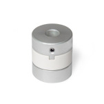
Product description
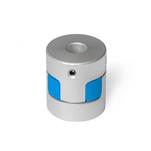
Oldham couplings GN 2243 can compensate for large lateral shaft misalignments while transmitting high torques. As a result, they are used in applications with a focus on pure torque and power transmission associated with high lateral shaft misalignments.
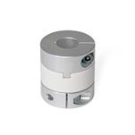
The use of set screws for clamping and the simple plug-in installation make oldham couplings very easy to assemble. They are suitable for a diverse range of applications and are used in general machine construction in packaging machines and pumps.
With the bore code K, the keyway is always integrated into both bores d2 and d3.
Specification
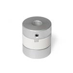
- Hub
AluminumAL
Anodized finish, natural color
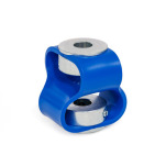
- Spacer
Plastic (Polyacetal POM)KU
Temperature resistant up to 176 °F (80 °C)
- Set screws
Steel, blackened finish- For d2 / d3 ≤ 4, one set screw
- For d2 / d3 > 4, two set screws
- Temperature range from:
-4 °F up to +176 °F (-20 °C up to +80 °C)
RoHS