You are here:
Product Overview
3.1 Indexing, Locking, Blocking with Pins and Ball-Shaped Elements
Ball Plungers, Spring Plungers
GN 713 Side Thrust Pins
previous product
next product
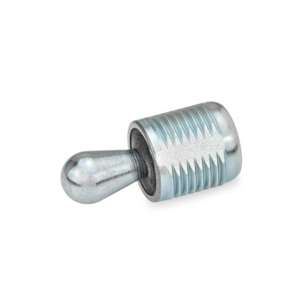
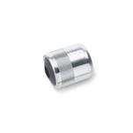
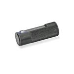
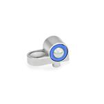
GN 713
Side Thrust Pins Steel Housing, Steel / Plastic Thrust Pin
Hide technical drawing
Part Options / Table
Type
SA Steel thrust pin, without seal
KA Plastic thrust pin, without seal
SB Steel thrust pin, with seal
KB Plastic thrust pin, with seal
Show / Hide columns
Part Number Part Number Part Number Part Number d1 Side thrust force F ≈ Type SA / SB Type KA / KB l1 -0.08 d2 l2 Type SA / KA Type SB / KB l3 Type SA / KA Type SB / KB s wType SA / KA Type SB / KB Part number
0.20
0.24
0.39
4.50 lbf (20 N)
11.24 lbf (50 N)
22.48 lbf (100 N)
8.99 lbf (40 N)
16.86 lbf (75 N)
33.72 lbf (150 N)
46.09 lbf (205 N)
4.50 lbf (20 N)
8.99 lbf (40 N)
22.48 lbf (100 N)
0.45 -0.08
0.75 -0.08
1.04 -0.08
0.71 -0.08
1.24 -0.08
1.77 -0.08
M 12
M 18 x 1.5
0.25
0.41
0.67
0.24
0.39
0.63
0.15
0.29
0.47
0.14
0.28
0.43
0.39
0.63
0.06
0.08
0.13
0.03
0.04
0.06
713.1-5.6
713.1-10
713-5-20-11.5-KA 0.20 - 4.50 lbf (20 N) 0.45 -0.08 M 12 0.25 - 0.15 - 0.39 0.06 - 713.1-5.6
713-5-20-11.5-KB 0.20 - 4.50 lbf (20 N) 0.45 -0.08 M 12 - 0.24 - 0.14 0.39 - 0.03 713.1-5.6
713-5-20-11.5-SA 0.20 4.50 lbf (20 N) - 0.45 -0.08 M 12 0.25 - 0.15 - 0.39 0.06 - 713.1-5.6
713-5-20-11.5-SB 0.20 4.50 lbf (20 N) - 0.45 -0.08 M 12 - 0.24 - 0.14 0.39 - 0.03 713.1-5.6
713-5-50-11.5-SA 0.20 11.24 lbf (50 N) - 0.45 -0.08 M 12 0.25 - 0.15 - 0.39 0.06 - 713.1-5.6
713-5-50-11.5-SB 0.20 11.24 lbf (50 N) - 0.45 -0.08 M 12 - 0.24 - 0.14 0.39 - 0.03 713.1-5.6
713-5-100-11.5-SA 0.20 22.48 lbf (100 N) - 0.45 -0.08 M 12 0.25 - 0.15 - 0.39 0.06 - 713.1-5.6
713-5-100-11.5-SB 0.20 22.48 lbf (100 N) - 0.45 -0.08 M 12 - 0.24 - 0.14 0.39 - 0.03 713.1-5.6
713-5-20-19-KA 0.20 - 4.50 lbf (20 N) 0.75 -0.08 M 12 0.25 - 0.15 - 0.39 0.06 - 713.1-5.6
713-5-20-19-KB 0.20 - 4.50 lbf (20 N) 0.75 -0.08 M 12 - 0.24 - 0.14 0.39 - 0.03 713.1-5.6
713-5-20-19-SA 0.20 4.50 lbf (20 N) - 0.75 -0.08 M 12 0.25 - 0.15 - 0.39 0.06 - 713.1-5.6
713-5-20-19-SB 0.20 4.50 lbf (20 N) - 0.75 -0.08 M 12 - 0.24 - 0.14 0.39 - 0.03 713.1-5.6
713-5-50-19-SA 0.20 11.24 lbf (50 N) - 0.75 -0.08 M 12 0.25 - 0.15 - 0.39 0.06 - 713.1-5.6
713-5-50-19-SB 0.20 11.24 lbf (50 N) - 0.75 -0.08 M 12 - 0.24 - 0.14 0.39 - 0.03 713.1-5.6
713-5-100-19-SA 0.20 22.48 lbf (100 N) - 0.75 -0.08 M 12 0.25 - 0.15 - 0.39 0.06 - 713.1-5.6
713-5-100-19-SB 0.20 22.48 lbf (100 N) - 0.75 -0.08 M 12 - 0.24 - 0.14 0.39 - 0.03 713.1-5.6
713-5-20-26.5-KA 0.20 - 4.50 lbf (20 N) 1.04 -0.08 M 12 0.25 - 0.15 - 0.39 0.06 - 713.1-5.6
713-5-20-26.5-KB 0.20 - 4.50 lbf (20 N) 1.04 -0.08 M 12 - 0.24 - 0.14 0.39 - 0.03 713.1-5.6
713-5-20-26.5-SA 0.20 4.50 lbf (20 N) - 1.04 -0.08 M 12 0.25 - 0.15 - 0.39 0.06 - 713.1-5.6
713-5-20-26.5-SB 0.20 4.50 lbf (20 N) - 1.04 -0.08 M 12 - 0.24 - 0.14 0.39 - 0.03 713.1-5.6
713-5-50-26.5-SA 0.20 11.24 lbf (50 N) - 1.04 -0.08 M 12 0.25 - 0.15 - 0.39 0.06 - 713.1-5.6
713-5-50-26.5-SB 0.20 11.24 lbf (50 N) - 1.04 -0.08 M 12 - 0.24 - 0.14 0.39 - 0.03 713.1-5.6
713-5-100-26.5-SA 0.20 22.48 lbf (100 N) - 1.04 -0.08 M 12 0.25 - 0.15 - 0.39 0.06 - 713.1-5.6
713-5-100-26.5-SB 0.20 22.48 lbf (100 N) - 1.04 -0.08 M 12 - 0.24 - 0.14 0.39 - 0.03 713.1-5.6
713-6-40-11.5-KA 0.24 - 8.99 lbf (40 N) 0.45 -0.08 M 12 0.41 - 0.29 - 0.39 0.08 - 713.1-5.6
713-6-40-11.5-KB 0.24 - 8.99 lbf (40 N) 0.45 -0.08 M 12 - 0.39 - 0.28 0.39 - 0.04 713.1-5.6
713-6-40-11.5-SA 0.24 8.99 lbf (40 N) - 0.45 -0.08 M 12 0.41 - 0.29 - 0.39 0.08 - 713.1-5.6
713-6-40-11.5-SB 0.24 8.99 lbf (40 N) - 0.45 -0.08 M 12 - 0.39 - 0.28 0.39 - 0.04 713.1-5.6
713-6-75-11.5-SA 0.24 16.86 lbf (75 N) - 0.45 -0.08 M 12 0.41 - 0.29 - 0.39 0.08 - 713.1-5.6
713-6-75-11.5-SB 0.24 16.86 lbf (75 N) - 0.45 -0.08 M 12 - 0.39 - 0.28 0.39 - 0.04 713.1-5.6
713-6-100-11.5-SA 0.24 22.48 lbf (100 N) - 0.45 -0.08 M 12 0.41 - 0.29 - 0.39 0.08 - 713.1-5.6
713-6-100-11.5-SB 0.24 22.48 lbf (100 N) - 0.45 -0.08 M 12 - 0.39 - 0.28 0.39 - 0.04 713.1-5.6
713-6-40-19-KA 0.24 - 8.99 lbf (40 N) 0.75 -0.08 M 12 0.41 - 0.29 - 0.39 0.08 - 713.1-5.6
713-6-40-19-KB 0.24 - 8.99 lbf (40 N) 0.75 -0.08 M 12 - 0.39 - 0.28 0.39 - 0.04 713.1-5.6
713-6-40-19-SA 0.24 8.99 lbf (40 N) - 0.75 -0.08 M 12 0.41 - 0.29 - 0.39 0.08 - 713.1-5.6
713-6-40-19-SB 0.24 8.99 lbf (40 N) - 0.75 -0.08 M 12 - 0.39 - 0.28 0.39 - 0.04 713.1-5.6
713-6-75-19-SA 0.24 16.86 lbf (75 N) - 0.75 -0.08 M 12 0.41 - 0.29 - 0.39 0.08 - 713.1-5.6
713-6-75-19-SB 0.24 16.86 lbf (75 N) - 0.75 -0.08 M 12 - 0.39 - 0.28 0.39 - 0.04 713.1-5.6
713-6-100-19-SA 0.24 22.48 lbf (100 N) - 0.75 -0.08 M 12 0.41 - 0.29 - 0.39 0.08 - 713.1-5.6
713-6-100-19-SB 0.24 22.48 lbf (100 N) - 0.75 -0.08 M 12 - 0.39 - 0.28 0.39 - 0.04 713.1-5.6
713-6-40-26.5-KA 0.24 - 8.99 lbf (40 N) 1.04 -0.08 M 12 0.41 - 0.29 - 0.39 0.08 - 713.1-5.6
713-6-40-26.5-KB 0.24 - 8.99 lbf (40 N) 1.04 -0.08 M 12 - 0.39 - 0.28 0.39 - 0.04 713.1-5.6
713-6-40-26.5-SA 0.24 8.99 lbf (40 N) - 1.04 -0.08 M 12 0.41 - 0.29 - 0.39 0.08 - 713.1-5.6
713-6-40-26.5-SB 0.24 8.99 lbf (40 N) - 1.04 -0.08 M 12 - 0.39 - 0.28 0.39 - 0.04 713.1-5.6
713-6-75-26.5-SA 0.24 16.86 lbf (75 N) - 1.04 -0.08 M 12 0.41 - 0.29 - 0.39 0.08 - 713.1-5.6
713-6-75-26.5-SB 0.24 16.86 lbf (75 N) - 1.04 -0.08 M 12 - 0.39 - 0.28 0.39 - 0.04 713.1-5.6
713-6-100-26.5-SA 0.24 22.48 lbf (100 N) - 1.04 -0.08 M 12 0.41 - 0.29 - 0.39 0.08 - 713.1-5.6
713-6-100-26.5-SB 0.24 22.48 lbf (100 N) - 1.04 -0.08 M 12 - 0.39 - 0.28 0.39 - 0.04 713.1-5.6
713-10-100-18-KA 0.39 - 22.48 lbf (100 N) 0.71 -0.08 M 18 x 1.5 0.67 - 0.47 - 0.63 0.13 - 713.1-10
713-10-100-18-KB 0.39 - 22.48 lbf (100 N) 0.71 -0.08 M 18 x 1.5 - 0.63 - 0.43 0.63 - 0.06 713.1-10
713-10-100-18-SA 0.39 22.48 lbf (100 N) - 0.71 -0.08 M 18 x 1.5 0.67 - 0.47 - 0.63 0.13 - 713.1-10
713-10-100-18-SB 0.39 22.48 lbf (100 N) - 0.71 -0.08 M 18 x 1.5 - 0.63 - 0.43 0.63 - 0.06 713.1-10
713-10-150-18-SA 0.39 33.72 lbf (150 N) - 0.71 -0.08 M 18 x 1.5 0.67 - 0.47 - 0.63 0.13 - 713.1-10
713-10-150-18-SB 0.39 33.72 lbf (150 N) - 0.71 -0.08 M 18 x 1.5 - 0.63 - 0.43 0.63 - 0.06 713.1-10
713-10-205-18-SA 0.39 46.09 lbf (205 N) - 0.71 -0.08 M 18 x 1.5 0.67 - 0.47 - 0.63 0.13 - 713.1-10
713-10-205-18-SB 0.39 46.09 lbf (205 N) - 0.71 -0.08 M 18 x 1.5 - 0.63 - 0.43 0.63 - 0.06 713.1-10
713-10-100-31.5-KA 0.39 - 22.48 lbf (100 N) 1.24 -0.08 M 18 x 1.5 0.67 - 0.47 - 0.63 0.13 - 713.1-10
713-10-100-31.5-KB 0.39 - 22.48 lbf (100 N) 1.24 -0.08 M 18 x 1.5 - 0.63 - 0.43 0.63 - 0.06 713.1-10
713-10-100-31.5-SA 0.39 22.48 lbf (100 N) - 1.24 -0.08 M 18 x 1.5 0.67 - 0.47 - 0.63 0.13 - 713.1-10
713-10-100-31.5-SB 0.39 22.48 lbf (100 N) - 1.24 -0.08 M 18 x 1.5 - 0.63 - 0.43 0.63 - 0.06 713.1-10
713-10-150-31.5-SA 0.39 33.72 lbf (150 N) - 1.24 -0.08 M 18 x 1.5 0.67 - 0.47 - 0.63 0.13 - 713.1-10
713-10-150-31.5-SB 0.39 33.72 lbf (150 N) - 1.24 -0.08 M 18 x 1.5 - 0.63 - 0.43 0.63 - 0.06 713.1-10
713-10-205-31.5-SA 0.39 46.09 lbf (205 N) - 1.24 -0.08 M 18 x 1.5 0.67 - 0.47 - 0.63 0.13 - 713.1-10
713-10-205-31.5-SB 0.39 46.09 lbf (205 N) - 1.24 -0.08 M 18 x 1.5 - 0.63 - 0.43 0.63 - 0.06 713.1-10
713-10-100-45-KA 0.39 - 22.48 lbf (100 N) 1.77 -0.08 M 18 x 1.5 0.67 - 0.47 - 0.63 0.13 - 713.1-10
713-10-100-45-KB 0.39 - 22.48 lbf (100 N) 1.77 -0.08 M 18 x 1.5 - 0.63 - 0.43 0.63 - 0.06 713.1-10
713-10-100-45-SA 0.39 22.48 lbf (100 N) - 1.77 -0.08 M 18 x 1.5 0.67 - 0.47 - 0.63 0.13 - 713.1-10
713-10-100-45-SB 0.39 22.48 lbf (100 N) - 1.77 -0.08 M 18 x 1.5 - 0.63 - 0.43 0.63 - 0.06 713.1-10
713-10-150-45-SA 0.39 33.72 lbf (150 N) - 1.77 -0.08 M 18 x 1.5 0.67 - 0.47 - 0.63 0.13 - 713.1-10
713-10-150-45-SB 0.39 33.72 lbf (150 N) - 1.77 -0.08 M 18 x 1.5 - 0.63 - 0.43 0.63 - 0.06 713.1-10
713-10-205-45-SA 0.39 46.09 lbf (205 N) - 1.77 -0.08 M 18 x 1.5 0.67 - 0.47 - 0.63 0.13 - 713.1-10
713-10-205-45-SB 0.39 46.09 lbf (205 N) - 1.77 -0.08 M 18 x 1.5 - 0.63 - 0.43 0.63 - 0.06 713.1-10
Filter combination produces no result.
Show / Hide columns
Metric
d1 Side thrust force F ≈ Type SA / SB Type KA / KB l1 -0.08 d2 l2 Type SA / KA Type SB / KB l3 Type SA / KA Type SB / KB s wType SA / KA Type SB / KB Part number
0.20
0.24
0.39
4.50 lbf (20 N)
11.24 lbf (50 N)
22.48 lbf (100 N)
8.99 lbf (40 N)
16.86 lbf (75 N)
33.72 lbf (150 N)
46.09 lbf (205 N)
4.50 lbf (20 N)
8.99 lbf (40 N)
22.48 lbf (100 N)
0.45
0.71
0.75
1.04
1.24
1.77
M 12
M 18 x 1.5
0.25
0.41
0.67
0.24
0.39
0.63
0.15
0.29
0.47
0.14
0.28
0.43
0.39
0.63
0.06
0.08
0.13
0.03
0.04
0.06
GN 713.1-5.6
GN 713.1-10
0.20 4.50 lbf (20 N) 11.24 lbf (50 N) 22.48 lbf (100 N) 4.50 lbf (20 N) 0.45 0.75 1.04 M 12 0.25 0.24 0.15 0.14 0.39 0.06 0.03 GN 713.1-5.6
0.24 8.99 lbf (40 N) 16.86 lbf (75 N) 22.48 lbf (100 N) 8.99 lbf (40 N) 0.45 0.75 1.04 M 12 0.41 0.39 0.29 0.28 0.39 0.08 0.04 GN 713.1-5.6
0.39 22.48 lbf (100 N) 33.72 lbf (150 N) 46.09 lbf (205 N) 22.48 lbf (100 N) 0.71 1.24 1.77 M 18 x 1.5 0.67 0.63 0.47 0.43 0.63 0.13 0.06 GN 713.1-10
Filter combination produces no result.
Build & Price
3D Product Configurator
Diameter d1
Side thrust force F (Type SA / SB)
Side thrust force F (Type KA / KB)
Thread engagement l1
Type
Diameter d1
Side thrust force F (Type SA / SB)
Side thrust force F (Type KA / KB)
Thread engagement l1
Type
Technical and Assembly Instructions
Selected Part
Part Number
Total (net)
US$16.20
In Stock: 2
In Stock
GN 713-5-20-11,5-KA GN 713-5-20-11,5-KB GN 713-5-20-11,5-SA GN 713-5-20-11,5-SB GN 713-5-50-11,5-SA GN 713-5-50-11,5-SB GN 713-5-100-11,5-SA GN 713-5-100-11,5-SB GN 713-5-20-19-KA GN 713-5-20-19-KB GN 713-5-20-19-SA GN 713-5-20-19-SB GN 713-5-50-19-SA GN 713-5-50-19-SB GN 713-5-100-19-SA GN 713-5-100-19-SB GN 713-5-20-26,5-KA GN 713-5-20-26,5-KB GN 713-5-20-26,5-SA GN 713-5-20-26,5-SB GN 713-5-50-26,5-SA GN 713-5-50-26,5-SB GN 713-5-100-26,5-SA GN 713-5-100-26,5-SB GN 713-6-40-11,5-KA GN 713-6-40-11,5-KB GN 713-6-40-11,5-SA GN 713-6-40-11,5-SB GN 713-6-75-11,5-SA GN 713-6-75-11,5-SB GN 713-6-100-11,5-SA GN 713-6-100-11,5-SB GN 713-6-40-19-KA GN 713-6-40-19-KB GN 713-6-40-19-SA GN 713-6-40-19-SB GN 713-6-75-19-SA GN 713-6-75-19-SB GN 713-6-100-19-SA GN 713-6-100-19-SB GN 713-6-40-26,5-KA GN 713-6-40-26,5-KB GN 713-6-40-26,5-SA GN 713-6-40-26,5-SB GN 713-6-75-26,5-SA GN 713-6-75-26,5-SB GN 713-6-100-26,5-SA GN 713-6-100-26,5-SB GN 713-10-100-18-KA GN 713-10-100-18-KB GN 713-10-100-18-SA GN 713-10-100-18-SB GN 713-10-150-18-SA GN 713-10-150-18-SB GN 713-10-205-18-SA GN 713-10-205-18-SB GN 713-10-100-31,5-KA GN 713-10-100-31,5-KB GN 713-10-100-31,5-SA GN 713-10-100-31,5-SB GN 713-10-150-31,5-SA GN 713-10-150-31,5-SB GN 713-10-205-31,5-SA GN 713-10-205-31,5-SB GN 713-10-100-45-KA GN 713-10-100-45-KB GN 713-10-100-45-SA GN 713-10-100-45-SB GN 713-10-150-45-SA GN 713-10-150-45-SB GN 713-10-205-45-SA GN 713-10-205-45-SB