 Original design
code: PA11 / PA12
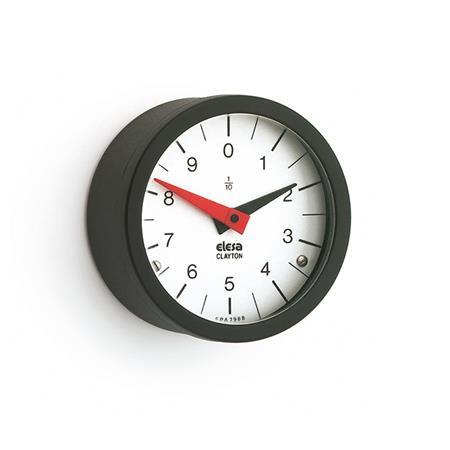
Product description
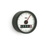
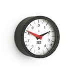
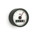
Position indicators EN 000.9 are suitable for installation in various types of operating elements.
Housing, and all internal components are produced from one single piece of material and ultrasonically welded assembly. They are spray waterproof and corrosion proof (Protection class IP 65).
The positive drive type installation allows the position indicator to be used in any position, even in applications with strong vibrations.
The reducing ratio shows the number of revolutions (long red pointer arm) required per 1 complete revolution of the short pointer arm.
Specification
Housing
Plastic, Polyamide (PA)
- Glass fiber reinforced
- Black, matte finish
Sight glass
Plastic, Polyamide (PA)
- Transparent
- Shock and aging resistant
Housing / Sight glass
- Operating temperature
32 °F to 212 °F (0 °C to +100 °C) - Oil and solvent proof (not suitable for alcohol)
Pointer arms
Plastic
- Long pointer arm: red
- Short pointer arm: black
Scale
Aluminum
- Matte, anodized finish
- Black graduation lines and numbers
Protection class IP 65
RoHS
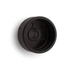
Accessory
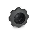
EN 534.9 Knurled Hand Knobs
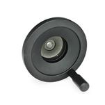
EN 577.9 Multi-Lobed Handwheels
GN 323.9 Solid Disk Handwheels
On request
- Special scales