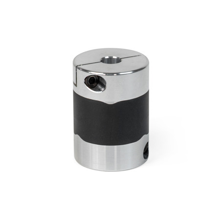
GN 2248 High Response Couplings Aluminum, Vulcanized, Vibration-Damping, with Clamping Hub

High Response Couplings GN 2248: Aluminum, Vulcanized, Vibration-Damping, with Clamping Hub

Product description

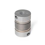
High response couplings GN 2248 transmit angular positions and torques with high precision and zero backlash. The elastomer element bonds the clamping hubs together, compensating for shaft misalignments and runout tolerances. The clamping hubs ensure easy installation.

High response couplings GN 2248 are primarily used in applications where precise position and motion transmission is required, e.g., in drive technology on test benches or similar applications.

Specification

Hub
AluminumAL


Elastomer element
Hydrogenated acrylonitrile butadiene rubberH
(HNBR)

  • Black
  • Hardness 75 ±5 Shore A

Operating temperature
-4 °F to +176 °F (-20 °C to +80 °C)


Socket cap screws ISO 4762
Steel, blackened finish


RoHS
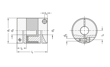
Hide technical drawing
GN 2248 Aluminum High Response Couplings, Vulcanized, Vibration-Damping, with Clamping Hub sketch

Part Options / Table

Bore code

BWithout keyway
Show / Hide columns

Metric

d1d2 - d3 H8
Recommended shaft tolerance h7
d4l1l2
Max. shaft insertion depth
l3l4
0.594-44-55-5---M 1.60.910.260.080.20
0.755-55-65-86-66-88-8M 21.020.300.100.26
0.986-66-86-108-88-1010-10M 2.51.260.370.130.35
1.188-88-108-1210-1010-1212-12M 31.420.430.160.43
1.5412-1212-1412-1614-1414-1616-16M 41.890.610.180.57
2.2020-2020-2525-25---M 52.360.770.220.79
Show / Hide columns
d1Tightening torque
of the screws
in Nm ≈
Rated torque
in Nm
Max.
rotational speed
(min-1)
Moment of inertia
in kgm2
Static
torsional stiffness
in Nm/rad
Max. shaft offset
Lateral
Axial in mmAngular
in °
0.590.251.1420002.3 x 10-7430.01± 0.21.5
0.750.52.1330006.9 x 10-7880.01± 0.21.5
0.9814250002.5 x 10-61400.01± 0.21.5
1.181.56.3210006 x 10-62200.01± 0.31.5
1.542.513.5160002.3 x 10-55200.01± 0.31.5
2.20735110001.2 x 10-415000.01± 0.31.5

Build & Price

Diameter d1
Bore code

Bore d2 - d3
Material (Hub)

Material (Elastomer element)

Diameter d1
Bore code

Bore d2 - d3
Material (Hub)

Material (Elastomer element)

Technical values

Show / Hide columns
d1Rated torque
in Nm
Max.
rotational speed
(rpm)
Moment of inertia
in kgm2
Static
torsional stiffness
in Nm/rad
Max. shaft offset
Lateral in mm

Axial in mm

Angular in °
151.1420002.3 x 10-7430.2± 0.21.5
192.1330006.9 x 10-7880.2± 0.21.5
254250002.5 x 10-61400.2± 0.21.5
306.3210006 x 10-62200.2± 0.31.5
3913.5160002.3 x 10-55200.2± 0.31.5
5635110001.2 x 10-415000.2± 0.31.5

Misalignment and Runout Tolerances

Like all mechanical parts, shafts are subjected to manufacturing and assembly tolerances that generally cannot be entirely eliminated even with extensive technical measures.
If these deviations are not taken into account in the design, the result can be vibrations, running noises, and wear or damage to the shafts and their bearings.
Suitable couplings not only are able to effectively compensate for misalignment and runout errors, they also greatly simplify the assembly process, thereby reducing the overall labor required.
Shaft misalignment and runout errors can vary in nature and should always be taken into consideration when selecting the appropriate coupling.

Error type

Misalignment diagram

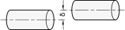
Lateral
The axes of the shafts are in fact parallel, but they are offset laterally and do not line up.

Misalignment diagram{St:_}Lateral

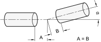
Angular
The axes of the shafts do not lie in the same plane; they meet at a certain angle.

Misalignment diagram{St:_}Angular

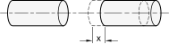
Axial
The shafts move axially along the axis of rotation.

Misalignment diagram{St:_}Axial

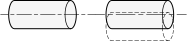
Runout
The shafts move radially out of the center of the axis of rotation.

Misalignment diagram{St:_}Runout

Shaft Insertion Depth

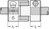
For correct fastening of the coupling hubs, the shaft must be installed according to the recommended shaft insertion depth l2. The shaft insertion depth l2 is specified in the standard sheet of the respective coupling.
If the insertion depth is too low, the shaft could slip out of the coupling, or the clamping hub could break. If the shaft is inserted too far, this can cause interference within the coupling, leading to damage.

Shaft Insertion Depth

Static torsional stiffness and temperature

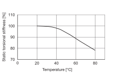
The diagrams show the change in static torsional stiffness within the permissible operating temperature range, under the assumption that the static torsional stiffness at 68°F (20 °C) is 100 percent. The torsional stiffness of the couplings decreases with increasing temperature.

4d91211b-1dc0-42ce-86ba-dea9111ce083

Restoring force – Eccentricity

When the shaft ends are installed in eccentric arrangements, the coupling constantly attempts to return to its neutral position. The resulting force is referred to as restoring force.
If the couplings are installed with the lowest possible eccentricity, the resulting restoring forces are lower. This also reduces the force acting on the shaft bearing.

1c04026b-818a-4c02-920f-1186d6237bf0

Restoring force – Pressure

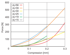
If the coupling is under pressure, subject to compressive load in the axial direction, it will strive to return to its neutral position. The force that counteracts the compressive force is referred to as restoring force.
Lowering the compression acting on a coupling results in a lower restoring force and less force exerted axially. This must always be taken into account in dimensioning the coupling.

3da3d355-b338-46bc-b37e-3780980a88db

Selected Part

Total (net)
US$77.20
Call / Email for Delivery Time
Save as Favorites
Recommend a product
Please note our quantity discounts (US Dollars).
MinMaxPrice
14US$77.20
59US$70.76
1024US$64.33
≥ 25US$57.90
Prop 65: Not compliant
WARNING:
Cancer and Reproductive Harm - www.P65Warnings.ca.gov
RoHS: Compliant
This article is RoHS-compliant in application of Annex III., which means it complies with EU Directive 2011/65/EU, including extension (2015/863/EU), for restricting the use of certain hazardous substances in electrical and electronic devices. The Directive regulates the use of hazardous substances in devices and components. The implementation in national law is summarily described with RoHS(Restriction of (the use of certain) hazardous substances)).
Weight: 0.019 lbs
If weight is not listed, please contact our Sales Department for additional information regarding weight.
Phone: 800-877-8351

CAD Download

Other Data Formats

Email CAD File

To receive an email with a CAD download without creating an account, please enter your e-mail address. Max of 3 CAD files per day unless you create an account.

CAD Download Tutorial About CAD Downloads

Need Help?

Our service team is available from Monday to Friday between 7:30 AM and 5:00 PM Central Time: 800-877-8351

Special Requests | Contact our sales team

GN 2248-15-B4-4-AL-HGN 2248-15-B4-5-AL-HGN 2248-15-B5-5-AL-HGN 2248-19-B5-5-AL-HGN 2248-19-B5-6-AL-HGN 2248-19-B5-8-AL-HGN 2248-19-B6-6-AL-HGN 2248-19-B6-8-AL-HGN 2248-19-B8-8-AL-HGN 2248-25-B6-6-AL-HGN 2248-25-B6-8-AL-HGN 2248-25-B6-10-AL-HGN 2248-25-B8-8-AL-HGN 2248-25-B8-10-AL-HGN 2248-25-B10-10-AL-HGN 2248-30-B8-8-AL-HGN 2248-30-B8-10-AL-HGN 2248-30-B8-12-AL-HGN 2248-30-B10-10-AL-HGN 2248-30-B10-12-AL-HGN 2248-30-B12-12-AL-HGN 2248-39-B12-12-AL-HGN 2248-39-B12-14-AL-HGN 2248-39-B12-16-AL-HGN 2248-39-B14-14-AL-HGN 2248-39-B14-16-AL-HGN 2248-39-B16-16-AL-HGN 2248-56-B20-20-AL-HGN 2248-56-B20-25-AL-HGN 2248-56-B25-25-AL-H

Your Contact

You are looking for a Winco partner near you?

JW Winco Services

Our service team is available from Monday to Friday between 7:30 AM and 5:00 PM Central Time

Request Callback